Product Details:
Payment & Shipping Terms:
|
| Other Name: | AUTO Power Relay | Contact Ratings: | 40A 14VDC |
|---|---|---|---|
| Max.switching Voltage: | 30VDC | Max.switching Current: | 40A |
| Max.switching Power: | 560W | Initial Contact Resistance: | 100mΩMax |
| Life Expectancy Electrical: | 100,000 Operations(rated Load) | Contact Material: | Ag Alloy |
| Highlight: | electromagnetic power relay,automotive starter relay |
||
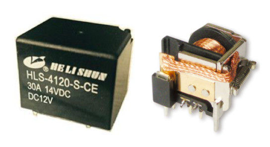
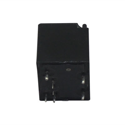
Automobile relay 4120 7pin SPDT 40A for car electrical control, 26*21*21mm
Description:
A relay is an electrically operated switch. Current flowing through the coil of the relay creates a magnetic field which attracts a lever and changes the switch contacts. The coil current can be on or off so relays have two switch positions and most have double throw (changeover) switch contacts.
What do you do when you want to switch on the light ?
you push on the switch….a little piece of metal connects the circutis….taddaaa light works, Relays are exactly the same….a switch, a little piece of metal that connects a circuit except that this switch is not triggered by your fingers, it is triggered by an electro-magnet. the electromagnet is a copper coil wounded around an iron piece, when this coil receives a small electric current, it turns into a magnet, this magnet moves the switch mechanically and press the switch on or off for you.
The main usage of relays is control….exactly like normal switches, you control a device ( say a big motor) to ON or OFF state.
Single Pole Double Throw (SPDT):
Such relay consists of a pair of coil pins, a common pin, a normally open (NO) pin and a normally closed (NC) pin. When the relay is not activated, the common pin is in contact with the NC pin and when it is activated, the common pin will break away from contact with the NC pin and subsequently makes contact with the NO pin. Also, when the relay is deactivated (from activated state), the common pin will conversely break away from contact with the NO pin and return back in contact with the NC pin.
Applications:
Relays are used in electronics to switch a smaller current which in turn will control larger current. They prevent the user to have direct contact to the main device being controlled that might be holding high voltage. These devices are comparable to a remote c ontrol which is used to make a big electronic equipment work.
General data:
| Contact form |
1A 1C |
| Insulation resistance | 100MΩMin at500VDC |
| Dielectric strength between open contacts | 500VAC 50-60HZ(1 minute) |
| Dielectric strength between contacts and coil | 750VAC 50-60HZ(1 minute) |
| Operate time | 5ms max. |
| Release time | 4ms max. |
| Ambient temperature | -40°C ~ +85°C |
| Shock resistance-Malfuction | 10G |
| Shock resistance-Destruction | 10G |
| Vibration resistance | 10-55Hz,1.5mm double amplitude |
| Ambient humidity | 40-85% RH |
| Weight | Approx 30g |
Coil data (@20°C)
|
Rated voltage (VDC) |
Coil Resistance Ω(±10%) |
Max Operate Voltage (VDC) | Min Release Voltage (VDC) | Max Applied Voltage (VDC) |
| 1.6W | ||||
| 6 | 23 | 3.9 | 0.6 | 7.8 |
| 12 | 90 | 7.8 | 1.2 | 15.6 |
| 24 | 360 | 15.6 | 2.4 | 31.2 |
CAUTION:
1.The use of any coil voltage less than the rated coil voltage will compromise the operation of the relay.
2.Pickup and release voltage are for test purposes only and are not to be used as design criteria.
3.Unless otherwise stated, the rated coil voltage specified in coil parameter tableshall be used for all tests and its application to the relay
Outline dimension(mm):
![]()
PCB board layout and Wiring diagram:
![]()
Contact Person: Mr. Roy Zhang
Tel: 86 574 55878090
Fax: 86-574-55878097