Product Details:
Payment & Shipping Terms:
|
| Other Name: | Single Phase Diode Bridge Rectifier | Reverse Voltage: | 1000V |
|---|---|---|---|
| Forward Current: | 10.0A | Number Of Elements: | 4 |
| Mounting Position: | Any | Tjmax.: | 150℃ |
| Highlight: | silicon bridge rectifier,bridge type rectifier |
||
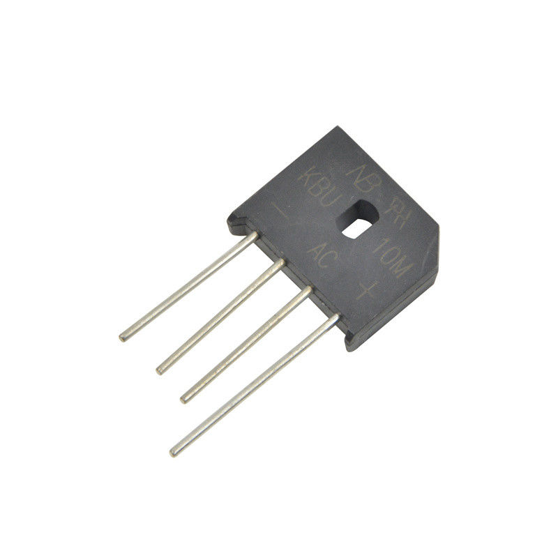
Through hole single phase type bridge rectifier KBU10M 10A 1000V
Description:
A bridge rectifier is an array of semiconductor diodes configured as a bridge that acts to change AC (alternating current) to full-wave pulsating DC (direct current). It is used in many electronic devices including laptop computers, cellular phones and PDA's. Depending on how you're viewing the electronic component, the four diodes form a square or diamond pattern. In a single-phase bridge rectifier, there are four diodes; in a 3 phase bridge rectifier, there are six diodes.
When AC current is connected across one diagonal, DC current is available across the other diagonal. The four diodes allow full-wave rectification without the need for a center-tap on the transformer.
Rectifier circuits are classified into two major groups i.e., single phase and three phases. In both cases they are again classified into three main categories those are uncontrolled, half controlled and fully controlled. If we use diode to convert this voltage we can call that as uncontrolled, instead if we use power electronic components like SCRS we can call as controlled rectifiers. We can control half wave or full wave according to the application dependency.
Features:
• Surage overload rating-200 amperes peak
• Ideal for printed circuit board
• Reliabe low cost construction utilizing molded plastic technique
• Plastic material has Underwriters Laboratory Flammability Classification 94V-0
• Compliant to RoHS
• Mounting position :Any
• Mounting torgue: 5 In.lb.max.
Application:
The primary application of bridge rectifiers is to transform an AC supply into DC power. All electronic devices require direct current, so bridge rectifiers are used inside the power supplies of almost all electronic equipment. Bridge rectifiers are also used for detecting the amplitude of modulated radio signals. The signal may be amplified before it is detected. If it is not, then a very low voltage drop diode or a diode biased with a fixed voltage must be used. Rectifiers are also used to supply polarized voltage for welding applications. Control of the output current is required in such circuits, and this may be achieved by replacing some of the diodes in a bridge rectifier with thyristors, which are diodes whose voltage output can be regulated by switching on and off with phase fired controllers.
Maximum ratings and electrical characteristics:
Rating at 25℃ ambient temperature unless otherwise specified. Resistive or inductive load,60HZ.
For capacitive load, derate current by 20%
| Characteristics | Symbol | KBU2M | Unit |
| Maximum recurrent peak reverse voltage | VRRM | 1000 | V |
| Maximum RMS bridge input voltage | VRMS | 700 | V |
| Maximum DC blocking voltage | VDC | 1000 | V |
| Maximum average forward rectified output current. @Ta=100°C | I(AV) | 10.0 | A |
| Peak forward surage current 8.3ms single half sine-wave super impossed on rated load(JEDEC method) | IFSM | 200 | A |
| Maximum forward voltage drop per bridge element at 5.0A | VF | 1.0 | V |
| Maximum reverse current at rated DC blocking voltage per element @Ta=25°C | IR | 10.0 | uA |
| Typical Junction Capacitance Per Element | CJ | 250 | pF |
| Operating temperature rangeTJ | TJ | -55~150 | ℃ |
| Storage temperature range TA | TSTG | -55~150 | ℃ |
Dimension:(mm)
![]()
Contact Person: Mr. Roy Zhang
Tel: 86 574 55878090
Fax: 86-574-55878097